
How to Design Chuck with 3D CAD: Easy Guide
Quick Summary: Designing a chuck with 3D CAD involves planning your design, choosing CAD software, creating a base model, adding jaws and features, verifying dimensions and tolerances, and exporting for manufacturing or 3D printing. This step-by-step guide simplifies the process for beginners.
Ever felt limited by the available chuck designs? Want to create a custom chuck for your specific needs? Designing your own chuck with 3D CAD software might seem daunting, but it’s totally achievable with the right guidance. Many cyclists and DIY enthusiasts find themselves needing specialized chucks for unique bike maintenance tasks. Don’t worry, this guide breaks down the process into simple, manageable steps, so you can design your own chuck like a pro. Let’s get started and unleash your creativity!
Understanding Chuck Design Basics
Before diving into the software, let’s cover the essential components and design considerations of a chuck.
Key Components of a Chuck
A chuck typically consists of the following parts:
- Body: The main structure that provides support and houses the other components.
- Jaws: The parts that grip the workpiece. They can be designed for various shapes and sizes.
- Actuation Mechanism: The system that opens and closes the jaws. This can be manual (e.g., a screw) or powered (e.g., pneumatic).
- Mounting Interface: The part that attaches the chuck to a machine, such as a lathe or mill.
Design Considerations
Keep these factors in mind when designing your chuck:
- Material: Choose a material that can withstand the forces and wear involved in your application. Common choices include steel, aluminum, and hardened alloys.
- Accuracy: Determine the required precision for your chuck. This will influence the design and manufacturing tolerances.
- Gripping Force: Calculate the necessary force to securely hold the workpiece without damaging it.
- Workpiece Size: Design the chuck to accommodate the range of workpiece sizes you’ll be using.
- Manufacturing Method: Consider how the chuck will be manufactured (e.g., machining, 3D printing) and design accordingly.
Choosing the Right 3D CAD Software

Selecting the appropriate CAD software is crucial for a smooth design process. Here are a few popular options:
- Autodesk Fusion 360: A powerful, cloud-based CAD/CAM tool that’s free for hobbyists and startups. It offers robust modeling, simulation, and manufacturing capabilities.
- SolidWorks: An industry-standard CAD software known for its comprehensive features and user-friendly interface. It’s a great choice for professional use.
- Tinkercad: A free, browser-based CAD tool perfect for beginners. It’s simple to use and ideal for basic designs.
- FreeCAD: An open-source CAD software that offers a wide range of features and customization options.
For this guide, we’ll focus on Autodesk Fusion 360 due to its accessibility and powerful features.
Step-by-Step Guide: Designing a Chuck in Fusion 360

Follow these steps to create your own chuck design in Fusion 360:
Step 1: Setting Up Your Project
- Launch Fusion 360: Open the software and sign in to your Autodesk account.
- Create a New Project: Go to the “File” menu and select “New Project.” Name your project appropriately (e.g., “Custom Chuck Design”).
- Create a New Design: Within your project, click “New Design” to start a fresh canvas.
Step 2: Creating the Chuck Body
- Create a Sketch: Go to the “Create” menu and select “Create Sketch.” Choose a plane to sketch on (e.g., the XY plane).
- Draw the Base Profile: Use the “Circle” tool to draw a circle representing the outer diameter of the chuck body. Define the diameter based on your design requirements.
- Extrude the Profile: Finish the sketch and go to the “Create” menu. Select “Extrude” and choose the circle you just drew. Enter the desired height for the chuck body.
- Add Mounting Features: Create another sketch on the bottom face of the chuck body. Draw the necessary features for mounting the chuck to your machine (e.g., threaded holes, a central bore). Extrude these features to create the mounting interface.
Step 3: Designing the Jaws
- Create a Sketch: Create a new sketch on the top face of the chuck body.
- Draw the Jaw Profile: Use the “Line” and “Arc” tools to draw the profile of one jaw. Consider the shape of the workpieces you’ll be holding.
- Extrude the Jaw: Finish the sketch and extrude the jaw profile to create the 3D shape. Ensure the jaw extends far enough to grip the workpiece securely.
- Create Jaw Features: Add any necessary features to the jaw, such as serrations or grooves, to improve grip.
- Pattern the Jaws: Use the “Pattern” tool to create multiple jaws around the chuck body. Typically, chucks have three or four jaws.
Step 4: Implementing the Actuation Mechanism
- Plan the Mechanism: Decide on the type of actuation mechanism you want to use (e.g., screw-driven, cam-operated).
- Create Necessary Features: Add the required features to the chuck body and jaws to accommodate the actuation mechanism. This may include threaded holes, slots, or grooves.
- Model the Actuation Components: Design the individual components of the actuation mechanism, such as screws, levers, or cams.
- Assemble the Mechanism: Use the “Joint” tool to assemble the actuation components within the chuck body and jaws.
Step 5: Adding Finishing Touches
- Fillet and Chamfer: Use the “Fillet” and “Chamfer” tools to round off sharp edges and improve the appearance and usability of the chuck.
- Add Text and Labels: If desired, add text or labels to the chuck body to indicate specifications or branding.
- Apply Materials: Assign appropriate materials to the different components of the chuck to visualize the final product.
Step 6: Verifying Your Design
- Check Dimensions: Use the “Inspect” tool to verify that all dimensions are accurate and meet your design requirements.
- Analyze Tolerances: Consider the manufacturing tolerances and ensure that the design will function correctly even with slight variations in dimensions.
- Simulate Movement: If you’ve designed a movable actuation mechanism, use the “Motion Study” feature to simulate its movement and check for any interferences.
Tips for Designing a Robust Chuck

Here are some tips to ensure your chuck design is robust and reliable:
- Use Strong Materials: Choose materials that can withstand the forces and wear involved in your application.
- Reinforce Critical Areas: Add extra material or reinforcement to areas that are subject to high stress.
- Design for Manufacturability: Consider the manufacturing process and design the chuck to be easily produced.
- Test Your Design: Before manufacturing the chuck, create a prototype (if possible) and test it thoroughly.
Advanced Design Considerations

For more complex chuck designs, consider these advanced factors:
- Balancing: If the chuck will be used at high speeds, ensure it is properly balanced to minimize vibration.
- Cooling: For heavy-duty applications, incorporate cooling channels to dissipate heat.
- Dust Protection: Design the chuck to prevent dust and debris from entering the mechanism.
Manufacturing Your Chuck
Once you’re satisfied with your design, you can manufacture the chuck using various methods:
- Machining: Traditional machining techniques, such as milling and turning, can be used to create the chuck from solid stock.
- 3D Printing: 3D printing is a viable option for creating complex chuck designs, especially for prototyping or low-volume production.
If you choose machining, create detailed drawings with dimensions and tolerances for the machinist. If you opt for 3D printing, export the design as an STL file and use appropriate printing settings for the chosen material.
Example: Designing a Simple 3-Jaw Chuck
Let’s walk through a simplified example of designing a basic 3-jaw chuck:
- Create the Body: Start with a cylindrical body, about 50mm in diameter and 30mm tall. Add a central bore and mounting holes on the bottom.
- Design the Jaws: Create three identical jaws with a simple rectangular profile. Add serrations to the gripping surface.
- Implement Actuation: Use a central screw to move a wedge that pushes the jaws inward. Create the necessary slots and threads for the screw and wedge.
- Assemble: Assemble the components using joints in Fusion 360.
This simplified example provides a foundation for more complex designs.
Table: Common Chuck Materials and Their Properties
| Material | Pros | Cons | Typical Applications |
|---|---|---|---|
| Steel | High strength, good wear resistance | Heavy, can rust | General-purpose chucks, heavy-duty applications |
| Aluminum | Lightweight, good corrosion resistance | Lower strength than steel | Light-duty chucks, applications where weight is a concern |
| Hardened Alloy Steel | Excellent wear resistance, high hardness | Expensive, difficult to machine | High-precision chucks, demanding applications |
| Plastic (e.g., ABS, Nylon) | Lightweight, inexpensive, corrosion resistant | Low strength, poor heat resistance | Prototyping, light-duty applications |
Table: Comparison of CAD Software
| Software | Price | Ease of Use | Features | Best For |
|---|---|---|---|---|
| Autodesk Fusion 360 | Free for hobbyists/startups, paid for commercial use | Moderate | Comprehensive CAD/CAM, simulation, collaboration | Hobbyists, startups, professionals |
| SolidWorks | Paid | Moderate to High | Extensive features, industry-standard | Professionals, engineers |
| Tinkercad | Free | Easy | Basic modeling, simple interface | Beginners, students |
| FreeCAD | Free | Moderate | Open-source, customizable, wide range of features | Hobbyists, advanced users |
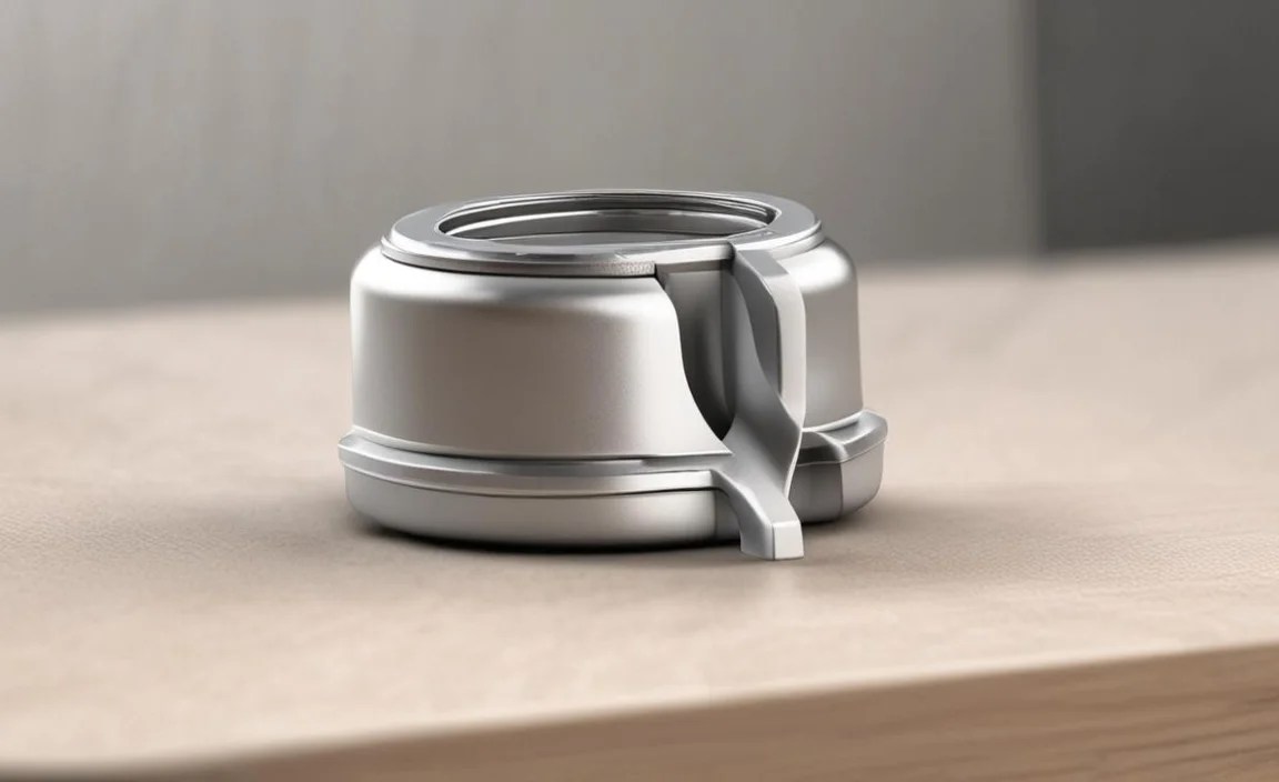
Visualizing Your Design with Renderings
Once your design is complete, use Fusion 360’s rendering capabilities to create realistic images of the chuck. This can help you visualize the final product and identify any potential issues.
- Switch to the Render Workspace: In Fusion 360, switch from the “Design” workspace to the “Render” workspace.
- Apply Appearances: Assign realistic appearances to the different components of the chuck (e.g., steel, aluminum, plastic).
- Adjust Lighting and Environment: Experiment with different lighting and environment settings to create the desired look.
- Render the Image: Click the “Render” button to generate a high-quality image of your design.
Collaborating with Others
Fusion 360’s cloud-based nature makes it easy to collaborate with others on your chuck design. You can share your design with colleagues or friends and work together in real-time.
- Share Your Design: Click the “Share” button in Fusion 360 to generate a public link to your design.
- Invite Collaborators: Invite specific individuals to collaborate on your design by entering their email addresses.
- Work Together: Collaborators can view, comment on, and edit your design in real-time.
FAQ: Designing a Chuck with 3D CAD
Here are some frequently asked questions about designing chucks with 3D CAD:
- What is the best CAD software for designing a chuck?
- Autodesk Fusion 360 is a great option due to its accessibility and powerful features. SolidWorks is also a popular choice for professional use.
- What materials are commonly used for chucks?
- Steel, aluminum, and hardened alloy steel are common choices, depending on the application and required strength.
- How do I determine the appropriate gripping force for my chuck?
- Calculate the necessary force based on the size, weight, and material of the workpieces you’ll be holding.
- Can I 3D print a chuck?
- Yes, 3D printing is a viable option, especially for prototyping or low-volume production. Choose a strong and durable material.
- What are the key components of a chuck?
- The main components are the body, jaws, actuation mechanism, and mounting interface.
- How do I ensure my chuck design is accurate?
- Use the “Inspect” tool in your CAD software to verify dimensions and analyze tolerances.
- What is an actuation mechanism?
- The actuation mechanism is the system that opens and closes the jaws of the chuck. It can be manual or powered.
Conclusion
Designing a chuck with 3D CAD might seem complex at first, but by following these steps and considering the key design factors, you can create a custom chuck tailored to your specific needs. Whether you’re a cyclist needing a specialized tool or a DIY enthusiast looking for a new challenge, mastering chuck design opens up a world of possibilities. So, grab your CAD software, unleash your creativity, and start designing!


